How parts are hung and racked for powder coating directly affects coating quality, transfer efficiency, production throughput, and defect rates. Poor racking leads to Faraday cage effects in recessed areas, inconsistent film thickness, visible contact marks in unacceptable locations, inadequate electrical grounding that prevents proper powder deposition, and wasted booth space that reduces throughput.
Guides
How to Hang Parts for Powder Coating: Rack Design, Grounding, and Throughput
Sundial Powder Coating·April 22, 2026·13 min
The electrostatic powder coating process requires that every part has a reliable electrical ground path from the part surface through the hanging hardware to the conveyor or rack system and ultimately to earth ground. Without this ground path, the electrostatic charge on the powder particles has no attraction to the part, and powder deposition is poor or nonexistent. Even a partially degraded ground path — caused by powder buildup on hooks, corroded contact points, or loose connections — reduces transfer efficiency and creates inconsistent coating thickness.
Ready to Start Your Project?
From one-off customs to 15,000-part production runs — get precise pricing in 24 hours.
On This Page
Why Part Hanging and Racking Matters for Powder Coating Quality
Racking also determines which surfaces of the part are accessible to the spray gun and which are shadowed by adjacent parts or rack components. Parts hung too close together create mutual Faraday effects that prevent powder from reaching inner surfaces. Parts hung at the wrong angle may trap powder in recesses or allow powder to accumulate excessively on horizontal surfaces.
This guide covers the principles and practices of effective part racking for powder coating, from basic hook selection through custom rack design for complex parts and high-volume production.
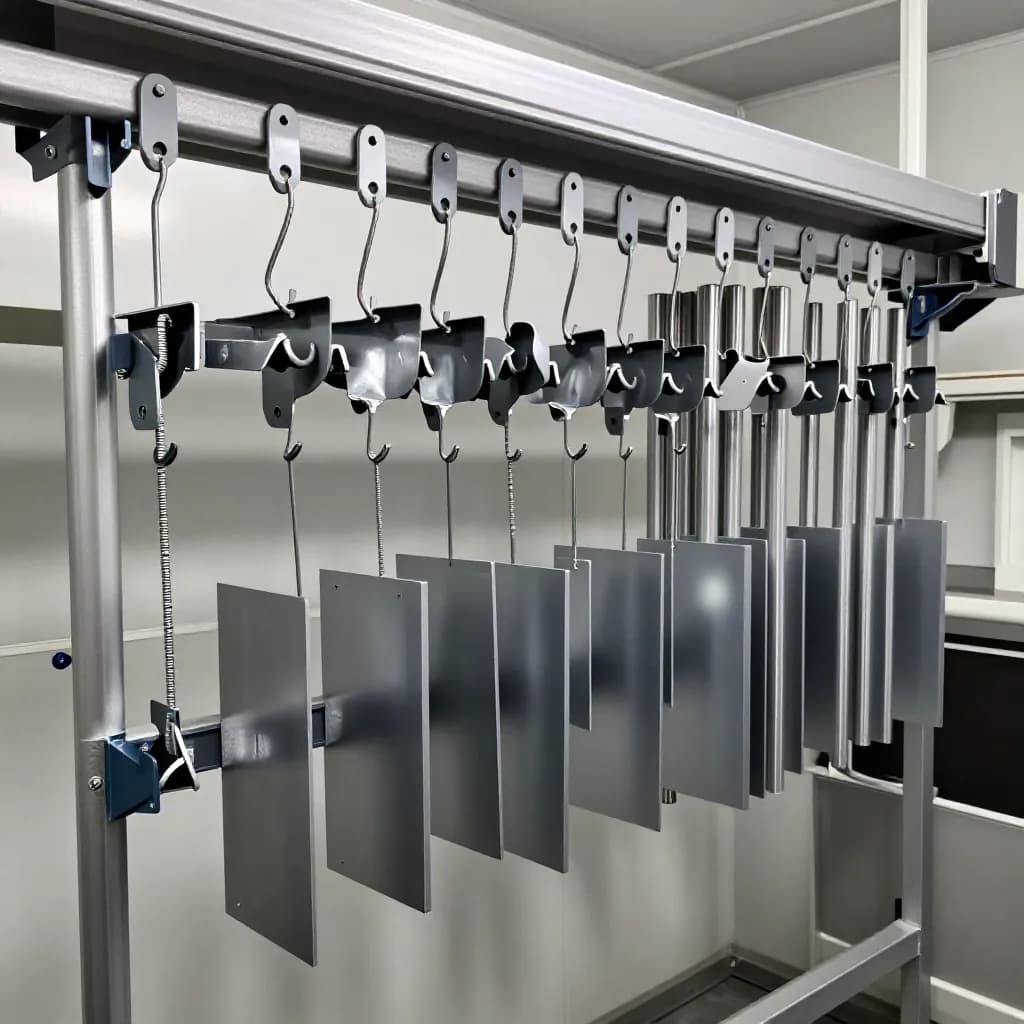
Rack and Hook Design Fundamentals
The simplest hanging method is a single hook — typically made from 4-8 mm diameter mild steel wire — that supports the part from a hole, slot, or edge. S-hooks, J-hooks, and custom-bent wire hooks are the most common types. The hook must be strong enough to support the part weight through the entire process including pretreatment, coating, and curing, and it must maintain reliable electrical contact with the part throughout.
For heavier parts or parts that require specific orientation, fabricated racks made from steel angle, flat bar, or tube provide more secure support and positioning. Rack designs range from simple frames with multiple hook positions to complex fixtures with adjustable supports, locating pins, and clamping mechanisms that hold parts in precise orientations.
The hook or rack contact point is where the hanging hardware touches the part. This point will not receive powder coating, leaving a small uncoated spot on the finished part. Contact points must be located in areas where the uncoated spot is acceptable — typically on hidden surfaces, mounting faces, or areas that will be covered by assembly hardware. The contact area should be as small as possible to minimize the uncoated zone while maintaining adequate support and electrical contact.
Rack material should be mild steel for most applications. Stainless steel racks are used in aggressive pretreatment environments but have higher material cost. Aluminum racks are lighter but cannot be stripped by burn-off and have lower strength. All rack materials accumulate powder coating over multiple cycles and must be stripped periodically to maintain electrical conductivity and prevent coating contamination from flaking rack coatings.
Electrical Grounding: The Foundation of Electrostatic Coating
Reliable electrical grounding is the single most important function of the racking system. The electrostatic powder coating process works by charging powder particles to a high negative potential (typically -60 to -100 kV) and relying on the electrostatic attraction between the charged particles and the grounded part to deposit the powder. If the ground path is compromised, this attraction is weakened and powder deposition suffers.
The ground path runs from the part surface through the hook or rack contact point, through the rack structure, through the conveyor hanger or rack support, through the conveyor system, and to earth ground. Every connection in this chain must be clean, tight, and conductive. A single high-resistance connection anywhere in the path degrades the entire ground circuit.
Powder buildup on hooks and racks is the most common cause of grounding problems. Each coating cycle deposits a thin layer of cured powder on the rack surfaces, including the contact points. After several cycles, this insulating layer becomes thick enough to significantly increase the resistance of the ground path. The result is reduced powder attraction, lower transfer efficiency, and inconsistent film thickness — often manifesting as thin or bare spots on parts that previously coated well.
To maintain grounding, strip racks regularly. The stripping frequency depends on the powder type and film thickness — some operations strip racks after every cycle, while others can go 5-10 cycles between strippings. Burn-off ovens, chemical strippers, and fluidized bed strippers are all used for rack stripping. Monitor ground path resistance with a megohmmeter — resistance should be below 1 megohm from the part contact point to earth ground. Many operations check ground resistance at the start of each shift as part of their standard startup procedure.
Part Orientation and Spacing for Optimal Coverage
Part orientation on the rack determines how powder reaches different surfaces and how gravity affects powder distribution during application and curing. The optimal orientation depends on the part geometry, the critical surfaces that require the best coating quality, and the direction of the powder spray.
As a general rule, orient parts so that the most critical surfaces face the spray guns directly. Surfaces that face away from the guns or are shadowed by other part features will receive less powder and may require additional manual touch-up passes. Vertical orientation is preferred for most parts because it allows excess powder to fall away rather than accumulating on horizontal surfaces, which can cause runs and sags during curing.
Angled orientation — tilting parts 10-15 degrees from vertical — can improve powder penetration into recessed features by changing the angle at which the powder stream enters the recess. This technique is particularly effective for channel sections, box sections, and parts with deep flanges that create Faraday cage effects when hung vertically.
Part spacing on the rack must balance coating quality against throughput. Parts hung too close together — less than 75-100 mm apart — create mutual electrostatic shielding that prevents powder from reaching inner surfaces and causes thin spots on facing surfaces. Parts hung too far apart waste booth space and reduce throughput. The optimal spacing depends on part geometry and size, but 100-150 mm between parts is a good starting point for most applications.
Consider the airflow pattern in the booth when positioning parts on the rack. Parts at the edges of the rack may receive different airflow than parts in the center, affecting powder distribution. Consistent part placement across the rack width helps maintain uniform coating quality across all parts in the batch.
Custom Rack Design for Complex Parts
Standard hooks work well for simple parts with convenient hanging features, but complex parts often require custom racks designed specifically for the part geometry. A well-designed custom rack pays for itself quickly through reduced masking time, fewer defects, faster loading and unloading, and improved coating consistency.
The custom rack design process starts with understanding the part requirements: which surfaces are critical, where contact points are acceptable, what orientation provides the best powder access to all surfaces, and how the part must be supported to prevent distortion during curing. Parts that are thin or flexible may require multiple support points to prevent sagging at curing temperatures.
Design the rack to minimize shadowing of the part surfaces by rack components. Rack members that run parallel to and close to the part surface block the spray pattern and create uncoated strips. Route rack structure away from critical surfaces, and use the minimum cross-section necessary for structural support. Round wire creates less shadow than flat bar of equivalent strength.
Incorporate features that speed loading and unloading. Locating pins or notches that position the part quickly and consistently eliminate the need for operators to judge placement by eye. Spring clips or gravity latches that secure the part without tools reduce handling time. Quick-release mechanisms allow rapid demasking and unloading at the end of the line.
Prototype custom racks before committing to production quantities. Build one or two racks, run test parts through the complete coating process, and evaluate the results before fabricating a full set. This prototyping step often reveals issues with access, grounding, or part fit that are not apparent from drawings alone. Adjust the design based on actual coating results before scaling up.
Rack Maintenance and Stripping Strategies
Rack maintenance is a continuous requirement in any powder coating operation. Racks accumulate cured powder coating with every cycle, and this buildup must be removed regularly to maintain electrical grounding, prevent coating contamination, and ensure proper part fit on the rack.
Burn-off ovens are the most common rack stripping method for steel racks. The oven heats the racks to 400-500°C, decomposing the cured powder coating to ash that is then removed by brushing or blasting. Burn-off is effective and relatively fast but subjects the racks to high temperatures that can cause warping and metal fatigue over time. Racks should be inspected for distortion after each burn-off cycle and straightened or replaced as needed.
Chemical stripping uses heated chemical solutions to dissolve cured powder coatings. It operates at lower temperatures than burn-off, reducing thermal stress on the racks, but requires longer processing times and generates chemical waste that must be managed. Chemical stripping is often preferred for racks with precise dimensions or heat-sensitive components.
Fluidized bed stripping combines heat and mechanical action — racks are heated in a bed of fluidized abrasive media that simultaneously softens and removes the coating. This method is faster than chemical stripping and gentler than burn-off, but the equipment is more expensive and requires more maintenance.
Establish a rack stripping schedule based on the number of coating cycles rather than calendar time. Track the number of cycles each rack has completed and strip when the accumulated coating thickness begins to affect grounding or part fit. Many operations color-code racks by stripping cycle to ensure even rotation through the stripping process. A systematic approach to rack maintenance prevents the gradual degradation of coating quality that occurs when racks are stripped only when problems become obvious.
Optimizing Throughput: Rack Density and Line Speed
Maximizing the number of parts processed per hour while maintaining coating quality is a key economic driver in powder coating operations. Rack density — the number of parts per linear meter of conveyor or per rack — is the primary lever for throughput optimization.
Start by mapping the booth opening dimensions and the effective spray zone. Parts must pass through the spray zone with sufficient dwell time for the guns to apply the required film thickness. The dwell time depends on the line speed, the number of guns, and the powder output per gun. Increasing rack density without adjusting gun settings or line speed may result in insufficient powder reaching parts in the center of a densely packed rack.
Double-sided racking — hanging parts on both sides of a central rack spine — effectively doubles the rack density compared to single-sided hanging. This approach works well when the booth has guns on both sides and the parts are thin enough that both sides can be coated simultaneously. For thicker parts or parts that require coating on all surfaces, single-sided racking with part rotation may be necessary.
Multi-level racking — hanging parts at two or three vertical levels on the same rack — increases density within the booth opening height. Ensure that parts on lower levels are not shadowed by parts above them and that the spray guns can reach all levels effectively. Adjustable gun positions or additional gun banks may be needed to cover multiple rack levels.
Track the relationship between rack density and first-pass quality. There is always a point of diminishing returns where adding more parts to the rack causes quality problems that require rework, negating the throughput gain. Find this balance point through systematic testing — increase density incrementally, measure first-pass yield at each density level, and set the production density at the point that maximizes good parts per hour rather than total parts per hour.
Frequently Asked Questions
How do you ground parts for powder coating?
Parts must have a continuous electrical path from the part surface through the hook or rack contact point, through the rack structure, and to earth ground. Every connection must be clean and conductive. Monitor ground resistance with a megohmmeter — it should be below 1 megohm. Strip racks regularly to remove insulating powder buildup from contact points.
Where should contact points be located on powder coated parts?
Contact points should be located on hidden surfaces, mounting faces, or areas that will be covered by assembly hardware. The contact area should be as small as possible while maintaining adequate support and electrical contact. Discuss acceptable contact point locations with the customer before production begins.
How far apart should parts be spaced on a powder coating rack?
Parts should be spaced 100-150 mm apart as a starting point. Parts closer than 75 mm create mutual electrostatic shielding that causes thin spots on facing surfaces. Optimal spacing depends on part geometry — larger or more complex parts may need greater spacing for adequate powder access to all surfaces.
How often should powder coating racks be stripped?
Stripping frequency depends on the powder type and film thickness applied. Some operations strip after every cycle, while others go 5-10 cycles between strippings. Track cycles per rack and strip when accumulated coating begins to affect grounding or part fit. Check ground resistance at the start of each shift.
What is the best rack material for powder coating?
Mild steel is the standard rack material for most operations. It provides good strength, reliable grounding, and can be stripped by burn-off, chemical, or fluidized bed methods. Stainless steel is used in aggressive pretreatment environments. Aluminum is lighter but cannot be stripped by burn-off and has lower strength.
Ready to Start Your Project?
From one-off customs to 15,000-part production runs — get precise pricing in 24 hours.