Powder coating application relies on electrostatic attraction to deposit dry powder particles onto grounded metal parts. The powder coating gun charges the powder particles — either by corona charging (high-voltage electrode at the gun tip) or tribo charging (frictional contact inside the gun barrel) — and directs them toward the grounded workpiece. The charged particles are attracted to the grounded surface and adhere electrostatically until they are melted and cured in the oven.
Guides
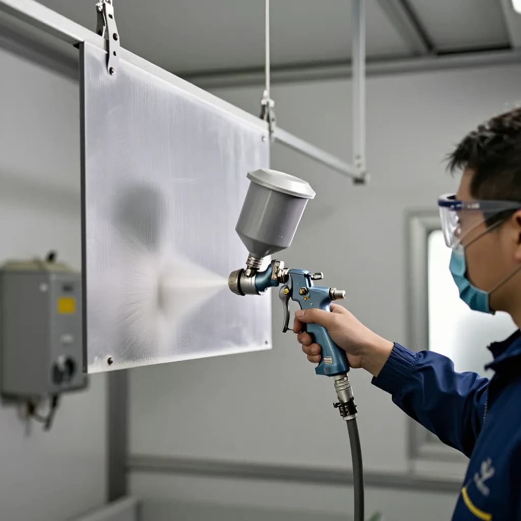
How to Apply Powder Coating: Gun Technique, Settings, and Application Mastery
Sundial Powder Coating·April 22, 2026·14 min
Corona charging is the most common method, used in approximately 85% of powder coating operations. The gun generates a high-voltage electric field (typically 60-100 kV) at the charging electrode, which ionizes the air and transfers charge to the powder particles as they pass through the field. Corona guns offer fast deposition rates, easy adjustment of charge level, and reliable performance across a wide range of powder types.
Ready to Start Your Project?
From one-off customs to 15,000-part production runs — get precise pricing in 24 hours.
On This Page
Understanding Electrostatic Powder Application Fundamentals
Tribo charging works by frictional contact between the powder particles and the interior surfaces of the gun barrel, typically made from PTFE. Tribo guns produce a softer, more uniform charge distribution on the particles, which results in better penetration into recessed areas and Faraday cage geometries. However, tribo charging is more sensitive to powder chemistry — it works best with specific resin types — and typically has lower deposition rates than corona guns.
Regardless of the charging method, the quality of the applied powder film depends on the operator's technique: gun distance, gun speed, pattern overlap, voltage and current settings, and powder flow rate. Mastering these variables is what separates a skilled powder coater from a novice.
Gun Distance and Spray Pattern Control
Gun-to-part distance is one of the most critical variables in powder application. The optimal distance for most corona guns is 150-300 mm (6-12 inches) from the gun tip to the part surface. This distance provides the best balance between powder deposition rate, film uniformity, and penetration into recessed areas.
At distances shorter than 150 mm, several problems emerge. The electric field intensity at the part surface becomes very high, causing back-ionization — a condition where the accumulated charge on the deposited powder layer repels incoming particles and creates a rough, orange-peel texture or even craters in the film. Short distances also concentrate the spray pattern into a small area, making it difficult to achieve uniform coverage without excessive overlap.
At distances greater than 300 mm, the electrostatic attraction weakens and powder deposition efficiency drops. More powder misses the part and enters the reclaim system, reducing transfer efficiency. The spray pattern becomes wider and more diffuse, which can be useful for light dusting passes but is inefficient for building film thickness.
The spray pattern shape is controlled by the deflector or nozzle at the gun tip. Flat spray nozzles produce a fan-shaped pattern that is ideal for coating flat panels and large surfaces. Conical deflectors produce a round pattern suited to general-purpose work on three-dimensional parts. The pattern width at the part surface depends on the gun distance and the deflector geometry — a typical flat spray nozzle produces a pattern 200-400 mm wide at the recommended gun distance.
Maintain a consistent gun distance throughout each pass. Varying the distance during a pass creates alternating bands of thick and thin coating that are visible in the finished film, particularly on flat surfaces with gloss or metallic finishes.
Voltage, Current, and Powder Flow Settings
The voltage setting on a corona gun controls the strength of the electrostatic field and the charge level on the powder particles. Higher voltage increases the electrostatic attraction and deposition rate but also increases the risk of back-ionization and Faraday cage effects. Lower voltage reduces these problems but slows deposition.
For most general-purpose application, start with the voltage at 60-80 kV and the current limit at 10-20 microamps. This provides good deposition rate with manageable back-ionization on flat and moderately recessed surfaces. For deep recesses, inside corners, and Faraday cage geometries, reduce the voltage to 30-50 kV and the current to 5-10 microamps. The lower field strength allows powder to penetrate into areas that would be shielded by the stronger field at higher settings.
Powder flow rate — controlled by the feed air and fluidizing air settings on the powder feed unit — determines how much powder is delivered to the gun per unit time. Typical flow rates for manual application are 100-300 grams per minute. Higher flow rates build film thickness faster but can overwhelm the electrostatic charging capacity of the gun, resulting in poorly charged particles that do not adhere well and contribute to overspray waste.
The atomizing air pressure at the gun controls the velocity of the powder cloud leaving the gun. Higher air pressure produces a faster, more focused powder stream that reaches the part with more kinetic energy. Lower air pressure produces a softer, more diffuse cloud that wraps around part features more gently. For most manual application, atomizing air pressure of 1.5-3.0 bar provides good results. Reduce air pressure when coating recessed areas to minimize the blowback effect where high-velocity air bounces off the recess walls and carries powder back out.
Document your settings for each powder type and part geometry. Powder coatings from different manufacturers and in different chemistries respond differently to electrostatic charging, and settings that work well for one powder may not be optimal for another.
Overlap, Travel Speed, and Building Uniform Film
Building a uniform powder film across the entire part surface requires systematic gun movement with consistent overlap between passes. The goal is to deposit a uniform layer of powder in the minimum number of passes, avoiding both thin spots from insufficient overlap and thick spots from excessive overlap.
The standard technique is to make horizontal passes across the part, moving the gun at a steady speed from one side to the other. Each pass should overlap the previous one by approximately 50% of the pattern width. This 50% overlap ensures that every point on the surface receives powder from two adjacent passes, creating a uniform film thickness. Less overlap creates visible banding; more overlap wastes powder and builds excessive thickness.
Travel speed should be consistent throughout each pass — typically 300-600 mm per second for manual application. Moving too slowly builds excessive thickness and increases the risk of back-ionization. Moving too fast deposits insufficient powder, requiring additional passes that slow production. The correct speed deposits the target film thickness in two to three complete coverage passes.
Start each pass before the gun reaches the part edge and continue past the opposite edge before reversing direction. This ensures that the edges of the part receive the same film thickness as the center. If the gun reverses direction while still over the part, the momentary pause at the reversal point creates a thick spot at the edge.
For three-dimensional parts, coat the most difficult areas first — inside corners, recesses, and Faraday areas — then build up the flat and convex surfaces. This approach ensures that the difficult areas receive adequate coverage before the easier surfaces accumulate enough charge to repel additional powder through back-ionization.
Conquering Faraday Cage Areas
Faraday cage effect is the most common challenge in electrostatic powder coating. It occurs when the electrostatic field lines concentrate on the outer edges and corners of a part, leaving recessed areas, inside corners, and enclosed spaces with little or no electrostatic attraction. The result is heavy powder buildup on edges and corners with thin or bare spots in recesses — the opposite of what is desired.
The physics behind the Faraday effect are straightforward: electrostatic field lines follow the path of least resistance, which is always to the nearest grounded surface. Inside a recess, the field lines converge on the edges of the opening rather than penetrating to the bottom. The deeper and narrower the recess, the more severe the Faraday effect.
Several gun technique adjustments help overcome Faraday areas. First, reduce the voltage to 30-50 kV when coating recesses. The lower field strength reduces the concentration of field lines on the edges and allows more powder to penetrate into the recess. Second, reduce the atomizing air pressure to minimize the blowback effect. Third, increase the gun distance slightly to spread the powder cloud over a wider area, allowing some particles to drift into the recess rather than being driven directly at the edges.
Tribo charging guns are inherently better at coating Faraday areas because they produce a softer, more uniform charge distribution without the strong directional field created by corona guns. If your product mix includes many parts with deep recesses, consider using tribo guns for those parts or as a dedicated touch-up tool for Faraday areas after the initial corona application.
Part orientation can also reduce Faraday effects. Tilting the part so that the recess opening faces the gun more directly allows the powder stream to enter the recess with less deflection. Rotating parts during coating — either manually or with a powered rotator — exposes different surfaces to the gun and improves overall coverage uniformity.
First Pass vs Touch-Up: A Two-Stage Application Strategy
Professional powder coaters often use a two-stage application strategy: a first pass that covers the entire part with a base layer of powder, followed by targeted touch-up passes that build thickness in areas that need additional coverage. This approach is more efficient and produces better results than trying to achieve perfect coverage in a single pass.
The first pass uses standard gun settings — 60-80 kV, moderate powder flow, and consistent travel speed — to deposit a uniform base layer across all accessible surfaces. This pass builds approximately 60-70% of the target film thickness on flat and convex surfaces. Do not try to force powder into Faraday areas during the first pass; the base layer on the outer surfaces will create back-ionization that makes subsequent penetration into recesses even more difficult.
After the first pass, switch to touch-up mode: reduce the voltage to 30-50 kV, reduce the powder flow rate, and reduce the atomizing air pressure. These lower settings allow powder to penetrate into recesses, inside corners, and other Faraday areas that received insufficient coverage during the first pass. Work slowly and deliberately, directing the gun into each recess and monitoring the powder buildup visually.
The visual appearance of the applied powder provides useful feedback during application. A uniform, velvety matte appearance indicates good coverage. Shiny or translucent areas indicate thin spots that need additional powder. Rough or textured areas may indicate back-ionization — reduce the voltage and allow the existing charge to dissipate before applying more powder.
For automatic application lines with reciprocating guns, the two-stage approach is implemented by programming different gun settings for different zones along the conveyor. The first zone applies the base coat at standard settings, and the second zone applies touch-up at reduced settings, often with guns positioned to target known Faraday areas on the specific parts being coated.
Common Application Defects and Gun Technique Corrections
Orange peel — a textured surface resembling the skin of an orange — is the most common application-related defect. While some orange peel is inherent to the powder formulation and cure process, excessive orange peel is often caused by applying powder too thick, using too high a voltage (causing back-ionization), or insufficient powder fluidization in the feed hopper. Correct by reducing film thickness to the specified range, lowering voltage, and checking the fluidization air setting.
Picture framing — heavy coating on edges and corners with thin coating in the center of flat panels — is caused by the electrostatic field concentrating on edges. Reduce voltage, increase gun distance, and use a wider spray pattern to distribute powder more evenly across the panel surface. On automatic lines, adjust gun positioning to direct more powder at the panel center.
Starving or thin spots in recesses are caused by Faraday cage effects as discussed above. Use the reduced-voltage touch-up technique, consider tribo charging for severe Faraday geometries, and optimize part orientation to improve access to recessed areas.
Powder spitting — intermittent surges of powder from the gun — is usually caused by moisture in the compressed air supply, clumped powder in the feed hopper, or a worn or damaged powder pump. Check the air dryer, break up any powder clumps in the hopper, and inspect the pump components. Spitting creates visible thick spots in the coating that cannot be corrected after curing.
Back-ionization — a rough, cratered surface caused by excessive charge buildup — occurs when too much powder is applied too quickly at too high a voltage. The accumulated charge on the powder layer exceeds the breakdown voltage of the air, creating micro-sparks that disrupt the powder surface. Reduce voltage, reduce powder flow rate, and allow more time between passes for charge to dissipate through the ground path.
Developing Operator Skill and Consistency
Powder coating application is a skill that improves with practice and deliberate attention to technique. New operators should start with simple, flat parts and standard powder colors before progressing to complex geometries and specialty finishes. A structured training program that covers the fundamentals of electrostatics, gun operation, and technique produces better results than learning by trial and error on production parts.
Establish standard operating procedures for each part type that specify gun settings, application sequence, number of passes, and target film thickness. These procedures provide a baseline that new operators can follow and experienced operators can refine. Document the procedures with photographs or videos showing the correct gun position, movement pattern, and visual appearance of properly applied powder at each stage.
Film thickness measurement during production provides immediate feedback on application quality. Measure film thickness on every part or on a statistical sample, and track the results on a control chart. Consistent film thickness within the specified range indicates good technique; high variability indicates inconsistent gun distance, travel speed, or overlap. Use the measurement data to identify operators who need additional training and to verify that process changes are producing the intended results.
Regular calibration and maintenance of the powder coating gun is essential for consistent application. Check the charging voltage with a kilovolt meter, verify the powder flow rate with a timed collection test, and inspect the gun tip, electrode, and deflector for wear and powder buildup. A gun that is not delivering the set voltage or flow rate will produce inconsistent results regardless of operator technique. Include gun calibration in the daily startup checklist and schedule comprehensive maintenance at regular intervals.
Frequently Asked Questions
What is the correct gun distance for powder coating?
The optimal gun-to-part distance for most corona guns is 150-300 mm (6-12 inches). Closer distances risk back-ionization and uneven coverage, while greater distances reduce transfer efficiency. Maintain consistent distance throughout each pass to avoid visible thickness variations in the finished coating.
What voltage should I use for powder coating?
Start at 60-80 kV for general flat and convex surfaces. Reduce to 30-50 kV for recessed areas, inside corners, and Faraday cage geometries. Lower voltage allows better powder penetration into difficult areas by reducing the concentration of electrostatic field lines on edges and corners.
How do you coat inside corners and recesses?
Reduce voltage to 30-50 kV, lower atomizing air pressure to minimize blowback, and increase gun distance slightly. Coat recesses after the first pass on flat surfaces, using a touch-up technique with reduced settings. Tribo charging guns provide inherently better penetration into Faraday cage areas than corona guns.
What causes orange peel in powder coating?
Excessive orange peel is typically caused by applying powder too thick, using too high a voltage (back-ionization), or poor powder fluidization. Correct by reducing film thickness to the specified range, lowering voltage, and ensuring proper fluidization in the feed hopper. Some orange peel is inherent to the powder formulation.
How much overlap should powder coating passes have?
Each pass should overlap the previous one by approximately 50% of the spray pattern width. This ensures every point on the surface receives powder from two adjacent passes, creating uniform film thickness. Less overlap causes visible banding; more overlap wastes powder and builds excessive thickness.
Ready to Start Your Project?
From one-off customs to 15,000-part production runs — get precise pricing in 24 hours.